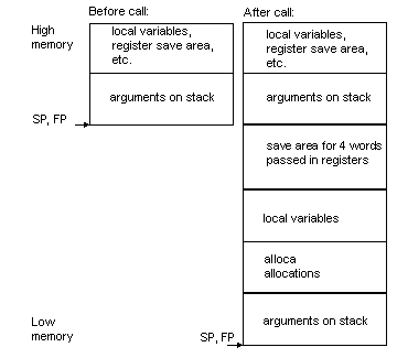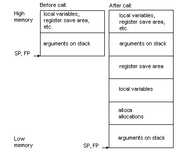
|
char :
|
1 byte
|
|
short :
|
2 bytes
|
|
int :
|
2 bytes unless -mint32, in
which case 4 bytes
|
|
long :
|
4 bytes
|
|
long long :
|
8 bytes
|
|
float :
|
4 bytes
|
|
double :
|
4 bytes unless -mdouble64,
in which case 8 bytes
|
|
long double :
|
8 bytes
|
|
pointer :
|
2 bytes
|
|
Volatile registers
|
r2 , r3 , r4
, r5 , r6 , r7 , r12 , r13
|
|
Saved registers
|
r6 , r7 , r8
, r9 , r10 , r11
|
|
Accumulators
|
a0 , a1
|
|
r0 through r3
|
function arguments/function return
|
|
r4
|
static chain register, not preserved
across calls
|
|
r5
|
not preserved across calls
|
|
r6 through r11
|
preserved across calls
|
|
r12
|
not preserved across calls
|
|
r13
|
holds return address, not preserved
across calls
|
|
r14
|
holds constant 0
|
|
r15
|
stack pointer, preserved across calls
|
|
a0 through a1
|
preserved across calls
|
|
psw
|
Processor Status Word
|
|
bpsw
|
Backup Processor Status Word
|
|
pc
|
Program Counter
|
|
bpc
|
Backup Program Counter
|
|
rpt_c
|
Repeat Count
|
|
rpt_s
|
Repeat Start address
|
|
rpt_e
|
Repeat End address
|
|
mod_s
|
Modulo Start address
|
|
mod_e
|
Modulo End address
|
|
iba
|
Instruction Break Address
|
|
f0
|
Flag 0
|
|
f1
|
Flag 1
|
|
c
|
Carry flag
|
|
cr0-cr15
|
Accepted as synonyms for these control
registers
|
There are no D10V specific linker command line options. See also Linker script.
For the D10V tools, the following linker
script is the default. Although this script is somewhat lengthy, it
is a generic script that will support all ELF situations. In practice,
sections like .rela.dtors are unlikely to be generated when compiling
using embedded ELF tools.
OUTPUT_FORMAT("elf32-d10v", "elf32-d10v", "elf32-d10v")
OUTPUT_ARCH(d10v)
ENTRY(_start)
SEARCH_DIR( <installation directory path> );
SECTIONS
{
/* Read-only sections, merged into text segment: */
. = 0x2000004;
.interp : { *(.interp) }
.hash : { *(.hash) }
.dynsym : { *(.dynsym) }
.dynstr : { *(.dynstr) }
.rel.text : { *(.rel.text) }
.rela.text : { *(.rela.text) }
.rel.data : { *(.rel.data) }
.rela.data : { *(.rela.data) }
.rel.rodata : { *(.rel.rodata) }
.rela.rodata : { *(.rela.rodata) }
.rel.got : { *(.rel.got) }
.rela.got : { *(.rela.got) }
.rel.ctors : { *(.rel.ctors) }
.rela.ctors : { *(.rela.ctors) }
.rel.dtors : { *(.rel.dtors) }
.rela.dtors : { *(.rela.dtors) }
.rel.init : { *(.rel.init) }
.rela.init : { *(.rela.init) }
.rel.fini : { *(.rel.fini) }
.rela.fini : { *(.rela.fini) }
.rel.bss : { *(.rel.bss) }
.rela.bss : { *(.rela.bss) }
.rel.plt : { *(.rel.plt) }
.rela.plt : { *(.rela.plt) }
.plt : { *(.plt) }
.rodata : { *(.rodata) *(.gnu.linkonce.r*) }
.rodata1 : { *(.rodata1) }
/* Adjust the address for the data segment. */
. = ALIGN(4);
.data : { *(.data) *(.gnu.linkonce.d*)
CONSTRUCTORS
}
.data1 : { *(.data1) }
.ctors : { *(.ctors) }
.dtors : { *(.dtors) }
.got : { *(.got.plt) *(.got) }
.dynamic : { *(.dynamic) }
/* We want the small data sections together, so single-instruction offsets can access them all, and initialized data all before uninitialized, so we can shorten the on-disk segment size. */
.sdata : { *(.sdata) }
_edata = .;
PROVIDE (edata = .);
__bss_start = .;
.sbss : { *(.sbss) *(.scommon) }
.bss : { *(.dynbss) *(.bss)
*(COMMON)
}
_end = . ;
PROVIDE (end = .);
/* Stabs debugging sections. */
.stab 0 : { *(.stab) }
.stabstr 0 : { *(.stabstr) }
.stab.excl 0 : { *(.stab.excl) }
.stab.exclstr 0 : { *(.stab.exclstr) }
.stab.index 0 : { *(.stab.index) }
.stab.indexstr 0 : { *(.stab.indexstr) }
.comment 0 : { *(.comment) }
/* DWARF debug sections. Symbols in the .debug DWARF section are relative to the beginning of the section so we begin .debug at 0. It's not clear yet what needs to happen for the others. */
.debug 0 : { *(.debug) }
.debug_info 0 : { *(.debug_info) }
.debug_abbrev 0 : { *(.debug_abbrev) }
.debug_line 0 : { *(.debug_line) }
.debug_frame 0 : { *(.debug_frame) }
.debug_srcinfo 0 : { *(.debug_srcinfo) }
.debug_aranges 0 : { *(.debug_aranges) }
.debug_pubnames 0 : { *(.debug_pubnames) }
.debug_sfnames 0 : { *(.debug_sfnames) }
.line 0 : { *(.line) }
/* These must appear regardless of . */
/* This sets the stack to the top of the simulator memory (i.e. top of 64K data space). */
.stack 0x2007FFE : { _stack = .; *(.stack) }
.text 0x1000000 :
{
*(.init)
*(.fini)
*(.text)
/* .gnu.warning sections are handled specially by elf32.em. */
*(.gnu.warning)
*(.gnu.linkonce.t*)
} =0
_etext = .;
PROVIDE (etext = .);
}
The following documentation discusses the use of the GNU debugger, GDB, with the D10V targets.
To specify the D10V simulator as the download target for debugging, use the GDB command, target sim, and to specify the D10V board as the download target, use the GDB command, target remote <port name>, where <port name> designates the port to which the board is attached.The following test program (trace.c)
illustrates tracing:
int a, c;
main()
{
int b, d, i;
a = 3;
b = 4;
c = 456 * (a + b);
b += c;
for (i = 0; i < 5; ++i)
{
a += d;
d = b * a;
}
}
(gdb) target remote /dev/ttyb |
Remote debugging using /dev/ttyb |
0x1000000 in _start () |
(gdb) load |
Loading section .data, size 0x190 vma 0x2000004 |
Loading section .text, size 0x1a8 vma 0x1000000 |
Start address 0x1000000 |
Transfer rate: 3296 bits/sec. |
(gdb) break main |
Breakpoint 1 at 0x1000048: file trace.c, line 7. |
(gdb) continue |
Continuing. |
Breakpoint 1, main () at trace.c:7 |
7 a = 3; |
(gdb) trace |
Tracing is now on. |
(gdb) step |
8 b = 4; |
(gdb) step |
9 c = 456 * (a + b); |
(gdb) step |
10 b += c; |
(gdb) info trace |
8 entries in trace buffer: |
0: 1 instruction at 0x1000048 |
1: 1 instruction at 0x100004c |
2: 1 instruction at 0x1000050 |
3: 1 instruction at 0x1000054 |
4: 1 instruction at 0x1000058 |
5: 1 instruction at 0x100005c |
6: 1 instruction at 0x1000060 |
7: 1 instruction at 0x1000064 |
Tracing is currently on. |
(gdb) untrace |
Tracing is now off. |
(gdb) tdisassemble |
Dump of trace from 0 to 8: |
7 a = 3; |
0x1000048 <main+8>: ldi.s r2, 0x3 || nop |
0x100004c <main+12>: st r2, @(0x196, r0)8 b = 4; |
0x1000050 <main+16>: ldi.s r2, 0x4 -> st r2, @r11 |
9 c = 456 * (a + b); |
0x1000054 <main+20>: ld r2, @(0x196, r0) |
0x1000058 <main+24>: ld r3, @r11 -> add r2, r3 |
0x100005c <main+28>: ldi.l r3, 0x1c8 |
0x1000060 <main+32>: nop || mul r2, r3 |
0x1000064 <main+36>: st r2, @(0x194, r0) End of trace dump. |
(gdb) |
(gdb) info trace |
11 entries in trace buffer: |
0: 8 instructions at 0x1000098 |
1: 3 instructions at 0x1000078 |
2: 12 instructions at 0x1000088 |
3: 3 instructions at 0x1000078 |
4: 12 instructions at 0x1000088 |
5: 3 instructions at 0x1000078 |
6: 12 instructions at 0x1000088 |
7: 3 instructions at 0x1000078 |
8: 12 instructions at 0x1000088 |
9: 4 instructions at 0x1000078 |
10: 1 instruction at 0x10000b8 |
Tracing is currently on. |
(gdb) tdisassemble 0 3 |
Dump of trace from 0 to 3: |
14 d = b * a; |
0x1000098 <main+88>: ld r2, @r11 || nop |
0x100009c <main+92>: ld r3, @(0x196, r0) |
0x10000a0 <main+96>: nop || mul r2, r3 |
0x10000a4 <main+100>: st r2, @(0x2, r11) |
11 for (i = 0; i < 5; ++i) |
0x10000a8 <main+104>: ld r2, @(0x4, r11) |
0x10000ac <main+108>: add3 r3, r2, 0x1 |
0x10000b0 <main+112>: st r3, @(0x4, r11) |
0x10000b4 <main+116>: bra.s 0x1000078 <main+56> || nop |
0x1000078 <main+56>: ld r2, @(0x4, r11) |
0x100007c <main+60>: cmpi.s r2, 0x5 || nop |
0x1000080 <main+64>: brf0t.l 0x1000088 <main+72> |
13 a += d; |
0x1000088 <main+72>: ld r2, @(0x196, r0) |
0x100008c <main+76>: ld r3, @(0x2, r11) |
0x1000090 <main+80>: add r2, r3 || nop |
0x1000094 <main+84>: st r2, @(0x196, r0) |
14 d = b * a; |
0x1000098 <main+88>: ld r2, @r11 || nop |
0x100009c <main+92>: ld r3, @(0x196, r0) |
0x10000a0 <main+96>: nop || mul r2, r3 |
0x10000a4 <main+100>: st r2, @(0x2, r11) |
11 for (i = 0; i < 5; ++i) |
0x10000a8 <main+104>: ld r2, @(0x4, r11) |
0x10000ac <main+108>: add3 r3, r2, 0x1 |
0x10000b0 <main+112>: st r3, @(0x4, r11) |
0x10000b4 <main+116>: bra.s 0x1000078 <main+56> || nop |
End of trace dump. |
(gdb) |
% d10v-elf-run -t hello.x |
0x00001d *L: ldi.s r0,0 --- 0x0000 :: 0x0000 F0=0 F1=0 C=0 |
0x00001d *R: nop |
0x00001e B: ldi.s r15,65534 --- 0xfffe :: 0xfffe F0=0 F1=0 C=0 |
0x00001f B: ldi.s r2,34920 --- 0x8868 :: 0x8868 F0=0 F1=0 C=0 |
0x000020 B: ldi.s r3,34952 --- 0x8888 :: 0x8888 F0=0 F1=0 C=0 |
0x000021 R: sub r3,r2 0x8888 0x8868 :: 0x002 F0=0 F1=0 C=0 |
0x000021 L: mv r4,r3 --- 0x0020 :: 0x0020 F0=0 F1=0 C=0 |
0x000022 L: srli r4,2 0x0020 0x0002 :: 0x0008 F0=0 F1=0 C=0 |
0x000022 R: mv r1,r0 --- 0x0000 :: 0x0000 F0=0 F1=0 C=0 |
0x000023 . . . |
% d10v-elf-run -v hello.x hello world! |
3 + 4 = 7 |
run hello.x |
executed 1458 instructions in the left container, 827 parallel, 15 nops |
executed 1450 instructions in the right container, 827 parallel, 810 nops |
executed 1344 long instructions |
executed 4252 total instructions |
Overlays support for the D10V targets
The following documentation discusses more of the overlay support.
SECTIONS
{
OVERLAY 0x1001000 : AT (0x8000)
{
.ovly0 { foo.o(.text) }
.ovly1 { bar.o(.text) }
}
OVERLAY 0x1002000 : AT (0x9000)
{
.ovly2 { baz.o(.text) }
.ovly3 { grbx.o(.text) }
}
[...]
SECTIONS
{
.ovly0 0x1001000 : AT (0x8000) { foo.o(.text) }
.ovly1 0x1001000 : AT (0x9000) { bar.o(.text) }
.ovly2 0x1002000 : AT (0xA000) { baz.o(.text) }
.ovly3 0x1002000 : AT (0xB000) { grbx.o(.text) }
[...]
.data :
{
[...]
_ovly_table = .;
LONG(ABSOLUTE(ADDR(.ovly0)));
LONG(SIZEOF(.ovly0));
LONG(LOADADDR(.ovly0));
LONG(0);
LONG(ABSOLUTE(ADDR(.ovly1)));
LONG(SIZEOF(.ovly1));
LONG(LOADADDR(.ovly1));
LONG(0);
LONG(ABSOLUTE(ADDR(.ovly2)));
LONG(SIZEOF(.ovly2));
LONG(LOADADDR(.ovly2));
LONG(0);
LONG(ABSOLUTE(ADDR(.ovly3)));
LONG(SIZEOF(.ovly3));
LONG(LOADADDR(.ovly3));
LONG(0);
_novlys = .;
LONG((_novlys - _ovly_table) / 16);
[...]
}
d10v-elf-gcc -g -Td10vdata.ld -oovlydata maindata.c ovlymgr.c
(gdb) file ovlydata |
Reading symbols from ovlydata...done. |
(gdb) target sim |
Connected to the simulator. |
(gdb) load |
Loading section .ovly0, size 0x2c lma 0x8000 |
Loading section .ovly1, size 0x2c lma 0x9000 |
Loading section .ovly2, size 0x2c lma 0xa000 |
Loading section .ovly3, size 0x2c lma 0xb000 |
Loading section .data00, size 0x4 lma 0xc000 |
Loading section .data01, size 0x4 lma 0xd000 |
Loading section .data02, size 0x4 lma 0xe000 |
Loading section .data03, size 0x4 lma 0xf000 |
Loading section .data, size 0x214 lma 0x2000004 |
Loading section .text, size 0x6e0 lma 0x1000000 |
Start address 0x1000000 |
Transfer rate: 19872 bits in <1 sec. |
(gdb) overlay auto |
(gdb) overlay list |
No sections are mapped. |
(gdb) info address foo |
Symbol "foo" is a function at address 0x1001000, |
-- loaded at 0x8000 in overlay section .ovly0. |
(gdb) info symbol 0x1001000 |
foo in unmapped overlay section .ovly0 |
bar in unmapped overlay section .ovly1 |
(gdb) info address bar |
Symbol "bar" is a function at address 0x1001000, |
-- loaded at 0x9000 in overlay section .ovly1. |
(gdb) break main |
Breakpoint 1 at 0x1000048: file maindata.c, line 18. |
(gdb) run |
Starting program: ovlydata |
Breakpoint 1, main () at maindata.c:18 |
18 OverlayLoad(0); |
(gdb) next |
19 OverlayLoad(4); |
(gdb) next |
20 a = foo(1); |
(gdb) overlay list |
Section .ovly0, loaded at 00008000 - 0000802c, mapped at 01001000 - 0100102c |
Section .data00, loaded at 0000c000 - 0000c004, mapped at 02001000 - 02001004 |
(gdb) info symbol 0x1001000 |
foo in mapped overlay section .ovly0 |
bar in unmapped overlay section .ovly1 |
(gdb) step |
foo (x=1) at foo.c:6 |
6 if (x) |
(gdb) x /i $pc |
0x1001008 <foo+8>: ld r2, @r11 -> cmpeqi.s r2, 0x0 |
(gdb) print foo |
$1 = {long int (int)} 0x1001000 <foo>
|
(gdb) print bar |
$2 = {long int (int)} 0x9000 <*bar*>
|
(gdb) disassemble |
Dump of assembler code for function foo: |
0x1001000 <foo>: st r11, @-sp -> subi sp, 0x2 |
0x1001004 <foo+4>: mv r11, sp -> st r2, @r11 |
0x1001008 <foo+8>: ld r2, @r11 -> cmpeqi.s r2, 0x0 |
0x100100c <foo+12>: brf0t.l 0x100101c <foo+28> |
0x1001010 <foo+16>: ld2w r2, @(0x1000, r0) |
0x1001014 <foo+20>: bra.l 0x1001024 <foo+36> |
0x1001018 <foo+24>: bra.l 0x1001024 <foo+36> |
0x100101c <foo+28>: ldi.s r2, 0x0 -> ldi.s r3, 0x0 |
0x1001020 <foo+32>: bra.l 0x1001024 <foo+36> |
0x1001024 <foo+36>: add3 sp, r11, 0x2 |
0x1001028 <foo+40>: ld r11, @sp+ -> jmp r13 |
End of assembler dump. |
(gdb) disassemble bar |
Dump of assembler code for function bar: |
0x9000 <*bar*>: st r11, @-sp -> subi sp, 0x2 |
0x9004 <*bar+4*>: mv r11, sp -> st r2, @r11 |
0x9008 <*bar+8*>: ld r2, @r11 -> cmpeqi.s r2, 0x0 |
0x900c <*bar+12*>: brf0t.l 0x901c <*bar+28*> |
0x9010 <*bar+16*>: ld2w r2, @(0x1000, r0) |
0x9014 <*bar+20*>: bra.l 0x9024 <*bar+36*> |
0x9018 <*bar+24*>: bra.l 0x9024 <*bar+36*> |
0x901c <*bar+28*>: ldi.s r2, 0x0 -> ldi.s r3, 0x0 |
0x9020 <*bar+32*>: bra.l 0x9024 <*bar+36*> |
0x9024 <*bar+36*>: add3 sp, r11, 0x2 |
0x9028 <*bar+40*>: ld r11, @sp+ -> jmp r13 |
End of assembler dump. |
(gdb) finish |
Run till exit from #0 foo (x=1) at foo.c:5 |
0x1000060 in main () at maindata.c:20 |
20 a = foo(1); |
Value returned is $3 = 324 |
(gdb) next |
21 OverlayLoad(1); |
(gdb) next |
22 OverlayLoad(5); |
(gdb) next |
23 b = bar(1); |
(gdb) overlay list |
Section .ovly1, loaded at 00009000 - 0000902c, mapped at 01001000 - 0100102c |
Section .data01, loaded at 0000d000 - 0000d004, mapped at 02001000 - 02001004 |
(gdb) info symbol 0x1001000 |
foo in unmapped overlay section .ovly0 |
bar in mapped overlay section .ovly1 |
(gdb) step |
bar (x=1) at bar.c:6 |
6 if (x) |
(gdb) x /i $pc |
0x1001008 <bar+8>: ld r2, @r11 -> cmpeqi.s r2, 0x0 |
(gdb) disassemble |
Dump of assembler code for function bar: |
0x1001000 <bar>: st r11, @-sp -> subi sp, 0x2 |
0x1001004 <bar+4>: mv r11, sp -> st r2, @r11 |
0x1001008 <bar+8>: ld r2, @r11 -> cmpeqi.s r2, 0x0 |
0x100100c <bar+12>: brf0t.l 0x100101c <bar+28> |
0x1001010 <bar+16>: ld2w r2, @(0x1000, r0) |
0x1001014 <bar+20>: bra.l 0x1001024 <bar+36> |
0x1001018 <bar+24>: bra.l 0x1001024 <bar+36> |
0x100101c <bar+28>: ldi.s r2, 0x0 -> ldi.s r3, 0x0 |
0x1001020 <bar+32>: bra.l 0x1001024 <bar+36> |
0x1001024 <bar+36>: add3 sp, r11, 0x2 |
0x1001028 <bar+40>: ld r11, @sp+ -> jmp r13 |
End of assembler dump. |
(gdb) finish |
Run till exit from #0 bar (x=1) at bar.c:5 |
0x100007c in main () at maindata.c:23 |
23 b = bar(1); |
Value returned is $4 = 309 |
(gdb) info addr bazx |
Symbol "bazx" is static storage at address 0x2002000, |
-- loaded at 0xe000 in overlay section .data02. |
(gdb) info sym 0x2002000 |
bazx in unmapped overlay section .data02 |
grbxx in unmapped overlay section .data03 |
(gdb) info addr grbxx |
Symbol "grbxx" is static storage at address 0x2002000, |
-- loaded at 0xf000 in overlay section .data03. |
(gdb) break baz |
Breakpoint 2 at 0x1002008: file baz.c, line 6. |
(gdb) break grbx |
Breakpoint 3 at 0x1002008: file grbx.c, line 6. |
(gdb) continue |
Continuing. |
Breakpoint 2, baz (x=1) at baz.c:6 |
6 if (x) |
(gdb) print &bazx |
$5 = (long int *) 0x2002000 |
(gdb) x /d &bazx |
0x2002000 <bazx>:317 |
(gdb) print &grbxx |
$6 = (long int *) 0xf000 |
(gdb) continue |
Continuing. |
Breakpoint 3, grbx (x=1) at grbx.c:6 |
6 if (x) |
(gdb) print &grbxx |
$7 = (long int *) 0x2002000 |
(gdb) x /d &grbxx |
0x2002000 <grbxx>:435 |
(gdb) print &bazx |
$8 = (long int *) 0xe000 |
(gdb) x /d &bazx |
0xe000 <*bazx*>:317 |
overlay manual
overlay map < section-name >
overlay unmap < section-name >
overlay list
overlay off
overlay auto
overlay list
overlay off
When this mode is activated, GDB will automatically read and interpret the data structures maintained in target memory by the overlay manager. To learn what overlays are mapped at any time, use the command, overlay list. Whenever the target program is allowed to run (by the STEP command), GDB will refresh its overlay map by reading from the target's overlay tables.
The automatic mapping may be temporarily overridden by the commands, overlay map and overlay unmap, but these mappings will last only until the next time the target is allowed to run. To explicitly take control of GDB's overlay mapping, switch to the overlay manual mode.
When GDB's overlay support (either manual or auto) is active, GDB's concept of a symbol's address is controlled by which overlays are mapped into which memory regions. For instance, if you use the command, PRINT, to get a variable that is in an overlay which is currently mapped (that is located in its runtime address region) GDB will fetch the variable's memory from the runtime address. If the variable's overlay is currently not mapped, GDB will fetch it from its load-time address.
Similarly, if you disassemble a function that is in an unmapped overlay, or use a symbol's address to examine memory, GDB will fetch the memory from the symbol's load-time address range instead of the runtime range. If GDB's output contains labels that are relative to an overlay's load-time address instead of the runtime address, the labels will be distinguished like this:
(gdb) overlay map .ovly0
(gdb) x /x foo
0x1001000 <foo>: 0x76bf81e5
(gdb) overlay unmap .ovly0
(gdb) x /x foo
0x8000 <*foo*>: 0x76bf81e5
(gdb) info address foo
Symbol "foo" is a function at address 0x1001000
-- loaded at 0x8000 in overlay section .ovly0.
(gdb) info symbol 0x1001000
foo in mapped overlay section .ovly0
bar in unmapped overlay section .ovly1