| Oracle Data Guard Concepts and Administration Release 2 (9.2) Part Number A96653-02 |
|


|
View PDF |
| Oracle Data Guard Concepts and Administration Release 2 (9.2) Part Number A96653-02 |
|
|
View PDF |
To reduce the load on your primary system, you can implement cascaded redo log destinations, whereby a standby database receives its redo logs from another standby database, instead of directly from the primary database. You can configure:
Figure D-1 shows cascaded redo logs to physical and logical standby databases.
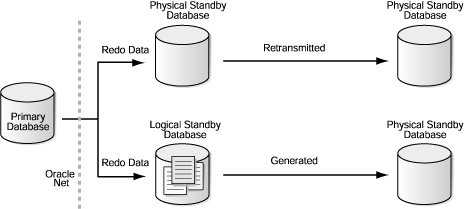
Text description of the illustration cascade.gif
A standby database can cascade redo data to up to nine destinations. This means that a Data Guard configuration potentially can contain up to 90 standby databases: 1 primary database with 9 standby databases, each of which in turn cascades redo data to 9 additional standby databases. However, from a practical perspective, only standby databases primarily intended to off-load reporting or backup operations typically would be configured to receive cascaded redo data. Standby databases that could potentially be involved in role transition operations typically are configured to receive redo data directly from the primary database and have LOG_ARCHIVE_DEST_n and LOG_ARCHIVE_DEST_STATE_n parameters defined so that when a switchover or failover operation occurs, logs continue to be received directly from the new primary database.
This appendix contains the following sections:
The following sections describe how to set up a Data Guard configuration to use cascaded redo log destinations:
To enable a physical standby database to send the incoming redo logs to another set of destinations, you must define the following items:
LOG_ARCHIVE_DEST_n initialization parameter on the primary database to set up a physical standby database that will be the starting point for a cascade to use the LGWR transport method. Use either SYNC or ASYNC network protocols depending on your requirements.At this point, you can begin defining the LOG_ARCHIVE_DEST_n initialization parameter on the physical standby database that will define the end points of the cascade. Remember, as part of the original setup of the physical standby database, you should have defined a local archive destination that will be used for local archiving when the physical standby database transitions to the primary role. For example, you might define the LOG_ARCHIVE_DEST_1 initialization parameter to be the`LOCATION=/physical1/arch' location. When the physical standby database switches roles, any archived redo logs will be put into that directory with the same format that you defined with the LOG_ARCHIVE_FORMAT initialization parameter. This local archiving destination can be the same as the one defined in the parameter STANDBY_ARCHIVE_DEST, but this is not required.
A side effect of this configuration is that the archive process on the standby database will now try to send the logs not only to the cascading end points but also to the other standby databases and the primary database if they are defined and enabled. This is not a problem, because the receiving database will either reject it if it is the primary database or a standby database that has already received the same log successfully. If the destination is another standby database and it has not received the log successfully, then this acts as an active gap resolution. You can avoid this by setting the state to DEFER for any destinations not involved in the cascade. However, you will have to remember to enable them again if you do a switchover or failover operation.
If you want to have one initialization parameter file to handle both the cascaded redo log destinations and the original primary and standby destinations, define the destinations for the primary database and other standby databases as well as the cascading standby databases. However, the total remote destinations still cannot exceed 10, including the local archiving destination.
Because it is the archiver process and not the log writer process that (during the archiving of the standby online redo logs) is sending the redo information to the cascaded redo log destinations, you are limited to one set of cascaded redo log destinations per standby database that is connected directly to the primary database.
A logical standby database that receives redo data directly from the primary database can be configured to cascade the redo data it generates (after it has filtered and applied the redo data it receives from the primary database) to other standby databases. Because redo data cascaded from a logical standby database is not identical to the redo data originally generated by the primary database, it cannot be applied to any standby database instantiated directly from the primary database. Instead, any standby databases that receives cascaded redo data from a logical standby database must be created from a copy of the logical standby database, and the following will be true:
For standby databases that receive cascaded redo data from a logical standby database, you must perform the same setup tasks as for a physical or logical standby database that receives redo data directly from the primary database. You can use any transport mode (LGWR or ARCH) and network protocol (SYNC or ASYNC). If you use the LGWR network protocol, you can optionally use standby online redo logs on your physical standby databases.
The following scenarios demonstrate configuration options and uses for cascaded redo log destinations.
You have a primary database in your corporate offices, and you want to create a standby database in another building on your local area network (LAN). In addition, you have a legal insurance requirement to keep the redo information and backup copies off-site at a geographically distant location outside of your LAN but on your wide area network (WAN).
You could define two destinations on your primary database so that redo logs could be transmitted to both of these sites, but this would put an extra workload on your primary database throughput due to the network latency of sending the redo logs over the WAN.
To solve this problem, you could define a tight connection between your primary and physical standby databases in your LAN using the LGWR and SYNC network transports and standby online redo logs. This would protect against losing access to the primary database and provide an alternate site for production when maintenance is required on the primary database. The secondary location on the WAN could be serviced by the physical standby database, ensuring that the redo information is stored off-site. Nightly backup operations on the production database could then be moved to the WAN remote standby database, which removes the requirement to ship tapes to the off-site storage area.
Finally, in a worst case scenario where you lose access to both the primary database and the physical standby database on the LAN, you could fail over to the remote standby database with minimal data loss. If you can gain access to the online redo log of the last standby database from the original standby database, you could recover it on the remote standby database, incurring no data loss.
The only time you would incur problems by sending the information over the WAN is during a switchover or failover operation, when the physical standby database has transitioned to the primary role. However, this configuration would still meet your insurance requirements.
You have a primary database in a remote city, and you would like to have access to its data locally for reporting purposes. The primary database already has a standby database set up for failure protection in an off-site location on the LAN. Putting a destination on the primary database to send the information to your site would adversely affect the performance of the primary database.
Solving this problem is similar to the solution that is described in scenario 1, except that you are sending the redo logs to a logical standby database, because you already have a physical standby database. First, ensure that:
If standby redo logs are not defined, you can define them dynamically on the standby database. The standby database will begin using the standby redo logs after the next log switch on the primary database. If the LGWR network transport is not being used, you can dynamically set log transport services on the primary database, and the primary database will start using the log writer at the next log switch.
Next, perform the normal setup tasks for a logical standby database. Any of the steps required to prepare to use a logical standby database must be done at the primary location as usual. After the logical standby database is up and running, define your destination parameters on the physical standby database to send the redo logs over the WAN, where they will be applied to the logical standby database.
A primary database located in a manufacturing site already is configured with two physical standby databases. One standby database is located on the LAN in another building, and the second standby database is more remotely located on a WAN in the corporate offices. You cannot use cascading standby databases for the standby database on the WAN, because there is a requirement to have two standby databases in no-data-loss mode. Also, the marketing department has requested access to the manufacturing data for sales predictions. The marketing department needs access to the data on a daily basis, and they want to combine sales data with manufacturing data to better understand sales versus the actual manufacturing times.
One solution would be to allow marketing to access a physical standby database in the corporate offices using read-only mode. However, putting the standby database in read-only mode requires stopping managed recovery operations. This means that the physical standby database can only catch up with the primary database at night, while it is still receiving data from the second and third shifts at the manufacturing plant. In addition, the standby database would always be at least 12 hours behind in applying redo logs. You could add another destination to the primary database to send the redo logs to a new logical standby database in the corporate offices. Because the systems used in the corporate office are different for the physical standby database and the proposed logical standby database, you cannot use the DEPENDENCY attribute when defining the standby destinations. Because redo logs need to be transmitted over a WAN, it would degrade performance on the primary database to send the redo data twice, which has been deemed to be unacceptable.
Cascaded redo log destinations can solve this problem. To set this up, you would create a logical standby database following the instructions in Chapter 4, but you would also set up the corporate physical standby database to transmit the redo logs over the corporate LAN to the new logical standby database. In this way, the primary database is only sending the data once over the WAN. The logical standby database could then be modified with new materialized views so that the marketing group can manage the data more efficiently. Because the logical standby database is open for read/write operations, the marketing group can add new schemas and load in sales data without affecting performance on the primary database, or the viability and current state of the physical standby database.
You have five Sales offices around the world, each with its own primary database. You would like to implement a failure protection strategy for all of them, as well as a way to get timely access to all data with minimal effect on each primary database.
To solve this problem, you would first implement a no-data-loss environment for each of the five offices by creating a physical standby database (with LGWR and SYNC attributes) local to each office. The physical standby databases could be on a LAN or a WAN. Then, create a logical standby database from each of the five primary databases and locate the logical standby databases in your corporate office. However, instead of having log transport services on each of the five primary databases send the redo logs, you would configure each of the five standby databases to send the redo logs to its logical standby database over the WAN. At one logical standby database (or all of them), you would define database links to each of the other logical standby databases and use them to access all of the sales data. If you decide that you do not need all of the information from each of the five primary databases, but only certain tables, you can use the SKIP routines to stop applying data that you do not need on each of the logical standby databases.
You have a primary database that is currently protected only by nightly backup operations. You have been told that you must implement a major failure recovery strategy immediately. You have another system of the same hardware type in-house, but it does not have enough power to serve as a standby database for failover purposes, and it does not have enough disks for the entire database. The only other system available to you that is large enough to hold the entire database is too far away to be put on the LAN, and the WAN that connects to it is extremely slow. The deadline for implementing the strategy is well before any network upgrades can occur. Adding a destination (on the primary database) to send the redo logs to the remote location would severely affect performance.
The interim solution to this problem would be to create a physical standby database on the remote system and create a distribution repository on the local smaller system. A distribution repository is comprised of only the standby control file and the standby database online redo logs, not the data files. You would configure the primary database to send the redo information to the repository locally using the log writer process (LGWR) in synchronous mode (SYNC). Because the connection is over the LAN, the effect on performance would be minimal. The repository would then be configured to send the data onwards over the WAN to the real standby database.
The risk with this configuration is that while the primary database has transmitted all of its data to a standby database, it is possible that the repository has not completed sending the data to the remote standby database at the time of a failure at the primary database. In this environment, as long as both systems do not fail at the same time, the remote standby database should receive all the data sent up to the last log switch. You would have to send the current online redo log manually.
Once the WAN is upgraded to permit a direct connection to the remote standby database, you can either redirect the destination to the repository to point to the remote standby database directly or create a new destination to the remote standby database and continue transmitting to the repository as an archive log repository.
|
 Copyright © 1998, 2002 Oracle Corporation. All Rights Reserved. |
|

